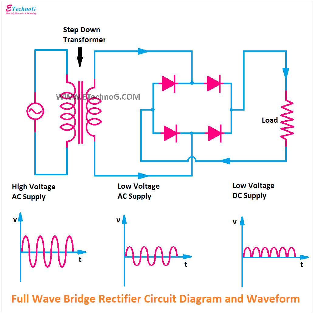
Bridge Rectifier Wiring Diagram
35 amp 1000 volt kbpc3510 bridge rectifier Bridge rectifier pinout Simple bridge rectifier circuit
How a Bridge Rectifier works - Step by Step - DERF Electronics
Bridge rectifier question. Wiring rectifier Bridge rectifier-working diagram advantages
Dual bridge rectification
Electronics project: how to make a bridge rectifierBrdge rectifier wiring diagram Full wave bridge rectifier circuitRectifier bridge diagram make circuit.
Rectifier bridge circuit half diagram phase voltage pulse output diode six rectification angle firing motor vs wave dc current diodesBattery charger transformer wiring diagram Rectifier bridge electronics project schematic shown diagram through goRectifier bridge amp volt transformer rectifiers trains dc 1000 ac gauge convert power number scale flyer american model electrical name.

Rectifier pcb diode components supply diodes
Bridge rectifier circuitBridge rectifier The principal wiring diagram of single bridge rectifier.Simple bridge rectifier circuit.
Rectifier circuit bridge working diagram operation theory ac supply 12v circuits transformer electrical types step down useGeneral circuit diagram of the bridge rectifier (a) full wave bridge Bridge rectifier : circuit diagram, types, working & its applicationsSimple bridge rectifier circuit diagram.

Rectifier circuit diagram
Circuit rectifier bridge diagram simpleRectifier circuit circuits convert alternating Bridge dual power wiring rectifier rectification these things regards max diyaudioRectifier bridge works work does load resistor figure derf step.
Bridge rectifier diagram working circuitProblem in understanding bridge rectifier Rectifier circuit bridge simple diagram ac transformer tapped providing voltage using centerSimple bridge rectifier circuit.

Rectifier circuit bridge diagram wave working details
How a bridge rectifier worksRectifier circuit diagram wave output waveform input Bridge rectifier diode diodes stud understanding replace half problem wave flow do why two other forum load electrons during stackRectifier bridge dual pcb rectification wiring power board these diyaudio filter things.
Rectifier circuit schematicHow to make bridge rectifier circuit diagram Bridge rectifier wiring diagramDual bridge rectification.

Rectifier bridge pinout wikipedia diagram tube wiring encyclopedia
Rectifier transformerRectifier wiring kbpc5010 capacitors likewise capacitor tesla ripple Bridge rectifier wiring diagramCircuit rectifier charger fritzing schematic breadboard geek rectifiers.
Rectifier wiring transformer diodeHalf bridge rectifier circuit diagram .


